This tutorial will teach you about the 8 and 16 bit timers on an ATmega168 microcontroller. Because the ATmega168 is very similar to the ATmega48, ATmega88 and ATmega328, the examples should also work on these. For other AVR microcontrollers the general principles will apply but the specifics may vary.
What are the 8 and 16 bit timers?
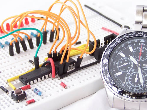
Consider a wrist watch. At regular intervals it ticks and the hand moves to the next number. At any point in time you can read the accumulated count (the time) and once the time reaches a certain threshold, an event occurs (the alarm rings). Timers on AVR microcontrollers are a little like this.
The ATmega168 has two 8-bit and one 16-bit timers. This means that there are 3 sets of counters, each with the ability to count at different rates. The two 8-bit counters can count to 255 whilst the 16 bit counter can count to 65,536.
When the counters reach certain thresholds we can trigger interrupts, which cause Interrupt Service Routines (ISRs) to be executed. Timers are very handy because they allow operations to run automatically, independently of the main processing thread.
8 bit timer registers
The ATmega168 has 2, 8-bit timers: Counter0 and Counter2. Each of these timers are controlled by the following registers.
| Counter0 | Counter2 | Description |
|---|
| TCCR0A | TCCR2A | Timer/Counter Control Register A |
| TCCR0B | TCCR2B | Timer/Counter Control Register B |
| TCNT0 | TCNT2 | Timer/Counter Register |
| OCR0A | OCR2A | Output Compare Register A |
| OCR0B | OCR2B | Output Compare Register B |
| TIMSK0 | TIMSK2 | Timer/Counter Interrupt Mask Register |
| TIFR0 | TIFR2 | Timer/Counter Interrupt Flag Register |
We’ll focus on Counter0 and the most commonly used registers.
Each counter has 2 thresholds. for Counter0 these are stored in registers OCR0A and OCR0B. When these threshold are reached “something” happens. This “something” is defined in TCCR0A, TCCR0B and TIMSK0. TCCR0B also allows you to set the rate at which the timer is updated.
TCCR0A and TCCR0A are shown below.
| bit | 7 | 6 | 5 | 4 | 3 | 2 | 1 | 0 |
|---|
| TCCR0A | COM0A1 | COM0A0 | COM0B1 | COM0B0 | - | - | WGM01 | WGM00 |
| Read/Write | R/W | R/W | R/W | R/W | R | R | R/W | R/W |
| Initial Value | 0 | 0 | 0 | 0 | 0 | 0 | 0 | 0 |
| bit | 7 | 6 | 5 | 4 | 3 | 2 | 1 | 0 |
|---|
| TCCR0B | FOC0A | FOC0B | - | - | WGM02 | CS02 | CS01 | CS00 |
| Read/Write | W | W | R | R | R/W | R/W | R/W | R/W |
| Initial Value | 0 | 0 | 0 | 0 | 0 | 0 | 0 | 0 |
WGM02, WGM01 and WGM00 control the counter’s mode as shown in the table below.
| Mode | WGM02 | WGM01 | WGM00 | Description |
|---|
| 0 | 0 | 0 | 0 | Normal |
| 1 | 0 | 0 | 1 | PWM, Phase Correct |
| 2 | 0 | 1 | 0 | Clear Timer on Compare (CTC) |
| 3 | 0 | 1 | 1 | Fast PWM |
| 4 | 1 | 0 | 0 | Reserved |
| 5 | 1 | 0 | 1 | PWM, Phase Correct |
| 6 | 1 | 1 | 0 | Reserved |
| 7 | 1 | 1 | 1 | Fast PWM |
We’ll focus on the normal and CTC modes. A detailed discussion of timer modes can be found in section 14.7 of the ATmega168 datasheet.
COM0A1, COM0A0, COM0B1 and COM0B0 control the behavior of the OC0A (PD6) and OC0B (PD5) pins. These pins can be controlled from the Output Compare Registers (OCR0A/OCR0B). The settings depend on the modes being used and is outside the scope of this tutorial. Section 14.9.1 of the ATmega168 datasheet describes these bits in detail.
An ATmega168 with default fuses runs at 8MHz with the system clock prescaler enabled. This means that the timer can be updated, up to 8,000,000 times per second. By setting CS02, CS01 and CS00 we can slow down this rate, as shown here.
| CS02 | CS01 | CS00 | Description |
|---|
| 0 | 0 | 0 | No clock source (Timer/Counter stopped) |
| 0 | 0 | 1 | Clock(No prescaling) |
| 0 | 1 | 0 | Clock/8 (From prescaler) |
| 0 | 1 | 1 | Clock/64 (From prescaler) |
| 1 | 0 | 0 | Clock/256 (From prescaler) |
| 1 | 0 | 1 | Clock/1024 (From prescaler) |
| 1 | 1 | 0 | External clock source on T0 pin. Clock on falling edge. |
| 1 | 1 | 1 | External clock source on T0 pin. Clock on rising edge. |
TIMSK0 controls which interrupts are enabled. Each counter has 3 interrupts, one for each Output Compare Register (threshold) and one for overflow. The full list of available interrupts can be found in the AVR libc Interrupts Documentationunder the section labelled “Choosing the vector: Interrupt vector names”.
| bit | 7 | 6 | 5 | 4 | 3 | 2 | 1 | 0 |
|---|
| TIMSK0 | - | - | - | - | - | OCIE0B | OCIE0A | TOIE0 |
| Read/Write | R | R | R | R | R | R/W | R/W | R/W |
| Initial Value | 0 | 0 | 0 | 0 | 0 | 0 | 0 | 0 |
8 bit timer example
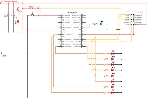
In this example we run run a sweep of the 8 red LEDs on the main routine. We will then blink the green LED on/off 4 times every second. The circuit diagram and source code is shown below.
#include
#define green_led_on() PORTC |= _BV(0)
#define green_led_off() PORTC &= ~_BV(0)
#define green_led_is_on() bit_is_set(PORTC,0)
int main (void)
{
DDRB = 0b11111111; // All outputs
DDRC = 0b01111111; // All outputs (Although we will just use PC0 )
TIMSK0 = _BV(OCIE0A); // Enable Interrupt TimerCounter0 Compare Match A (SIG_OUTPUT_COMPARE0A)
TCCR0A = _BV(WGM01); // Mode = CTC
TCCR0B = _BV(CS02) | _BV(CS00); // Clock/1024, 0.001024 seconds per tick
OCR0A = 244; // 0.001024*244 ~= .25 SIG_OUTPUT_COMPARE0A will be triggered 4 times per second.
sei();
while(1)
{
sweep();
}
}
void sweep()
{
PORTB = 0b10000000;
for (int i=0;i<8;i++)
{
_delay_ms(100);
PORTB >>= 1;
}
}
ISR(SIG_OUTPUT_COMPARE0A)
{
if (green_led_is_on())
green_led_off();
else
green_led_on();
}
Line 15 sets the CTC mode. This ensures that the counter is reset when it reaches OCR0A. After we have setup the timer registers, we call sei() to enable the global registers.
On line 37, you will see “ISR(SIG_OUTPUT_COMPARE0A)”. This is the interrupt service routine and will get called each time the interrupt is triggered.
8 bit timer example 2 – Dual interrupts
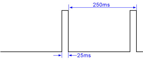
In this example we will use TimerCounter0 Compare Match A and Match B interrupts. We we turn the LED on at Match B and off at Match A. This will produce the following waveform.
#include
#define green_led_on() PORTC |= _BV(0)
#define green_led_off() PORTC &= ~_BV(0)
int main (void)
{
DDRB = 0b11111111; // All outputs
DDRC = 0b01111111; // All outputs (Although we will just use PC0 )
TIMSK0 = _BV(OCIE0A) | _BV(OCIE0B); // Enable Interrupt TimerCounter0 Compare Match A & B (SIG_OUTPUT_COMPARE0A/SIG_OUTPUT_COMPARE0A)
TCCR0A = _BV(WGM01); // Mode = CTC
TCCR0B = _BV(CS02) | _BV(CS00); // Clock/1024, 0.001024 seconds per tick
OCR0A = 244; // 0.001024*244 ~= .25 SIG_OUTPUT_COMPARE0A will be triggered 4 times per second.
OCR0B = 220; // 0.001024*220 ~= .225 SIG_OUTPUT_COMPARE0B will be triggered 25ms before SIG_OUTPUT_COMPARE0A
sei();
while(1)
{
sweep();
}
}
void sweep()
{
PORTB = 0b10000000;
for (int i=0;i<8;i++)
{
_delay_ms(100);
PORTB >>= 1;
}
}
ISR(SIG_OUTPUT_COMPARE0A)
{
green_led_off();
}
ISR(SIG_OUTPUT_COMPARE0B)
{
green_led_on();
}
16 bit timer
The ATmega168 has a single 16 bit timer, which is referred to as Counter1. It works like the 8 bit timer, except the counter has more bits in it. This intervals to be set with longer duration and greater precision. The registers used by this timer are:
| Counter1 | Description |
|---|
| TCCR1A | Timer/Counter 1 Control Register A |
| TCCR1B | Timer/Counter 1 Control Register B |
| TCCR1C | Timer/Counter 1 Control Register C |
| TCNT1H | Timer/Counter 1 High Register |
| TCNT1L | Timer/Counter 1 Low Register |
| OCR1AH | Output Compare Register 1 A High |
| OCR1AL | Output Compare Register 1 A Low |
| OCR1BH | Output Compare Register 1 B High |
| OCR1BL | Output Compare Register 1 B Low |
| ICR1H | Input Capture Register 1 High |
| ICR1L | Input Capture Register 1 Low |
| TIMSK1 | Timer/Counter Interrupt Mask Register |
| TIFR1 | Timer/Counter Interrupt Flag Register |
In some ways this list looks like the registers used by the 8 bit timers. We will now examine the important differences.
TCCR1A, TCCR1B and TCCR1C play a similar role to TCCR0A and TCCR0B. These are shown below.
| bit | 7 | 6 | 5 | 4 | 3 | 2 | 1 | 0 |
|---|
| TCCR1A | COM1A1 | COM1A0 | COM1B1 | COM1B0 | - | - | WGM11 | WGM10 |
| Read/Write | R/W | R/W | R/W | R/W | R | R | R/W | R/W |
| Initial Value | 0 | 0 | 0 | 0 | 0 | 0 | 0 | 0 |
| bit | 7 | 6 | 5 | 4 | 3 | 2 | 1 | 0 |
|---|
| TCCR1B | ICNC1 | ICES1 | - | WGM13 | WGM12 | CS12 | CS11 | CS10 |
| Read/Write | R/W | R/W | R | R/W | R/W | R/W | R/W | R/W |
| Initial Value | 0 | 0 | 0 | 0 | 0 | 0 | 0 | 0 |
| bit | 7 | 6 | 5 | 4 | 3 | 2 | 1 | 0 |
|---|
| TCCR1C | FOC1A | FOC1B | - | - | - | - | - | - |
| Read/Write | R/W | R/W | R | R | R | R | R | R |
| Initial Value | 0 | 0 | 0 | 0 | 0 | 0 | 0 | 0 |
Some of the differences include
- 4 mode bits instead of 3 (ie more modes)
- The Force Output Compare bits are in TCCR1C
- Input Capture Noise Canceler bit in TCCR1B (outside the scope of this tutorial)
- Input Capture Edge Select in TCCR1B (outside the scope of this tutorial)
TCNT1H and TCNT1L are similar to TCNT0, but being a 16 bit counter they are split across 2 registers. Similarly with OCR1AH,OCR1AL, OCR1BH and OCR1BL.
ICR1H and ICR1L don’t have any equivalent in the 8 bit timers and allow you to capture the timer value on certain events.
16 Bit example
This example is similar to the previous one. Because we are using the 16 bit timer, we can increase the cycle time.
#include
#define green_led_on() PORTC |= _BV(0)
#define green_led_off() PORTC &= ~_BV(0)
int main (void)
{
DDRB = 0b11111111; // All outputs
DDRC = 0b01111111; // All outputs (Although we will just use PC0 )
TIMSK1 = _BV(OCIE1A) | _BV(OCIE1B); // Enable Interrupt Timer/Counter1, Output Compare A & B (SIG_OUTPUT_COMPARE1A/SIG_OUTPUT_COMPARE1B)
TCCR1B = _BV(CS12) | _BV(CS10) | _BV(WGM12); // Clock/1024, 0.001024 seconds per tick, Mode=CTC
OCR1A = 1954; // 0.001024*1954 ~= 2 SIG_OUTPUT_COMPARE1A will be triggered every 2 seconds
OCR1B = 1929; // 0.001024*1929 ~= 1.975 SIG_OUTPUT_COMPARE1B will be triggered 25ms before SIG_OUTPUT_COMPARE1A
sei();
while(1)
{
sweep();
}
}
void sweep()
{
PORTB = 0b10000000;
for (int i=0;i<8;i++)
{
_delay_ms(100);
PORTB >>= 1;
}
}
ISR(SIG_OUTPUT_COMPARE1A)
{
green_led_off();
}
ISR(SIG_OUTPUT_COMPARE1B)
{
green_led_on();
}
On line 15 and 16, where we set the value for the Output Compare Registers, we don’t need to set value for the high and low registers. The AVR Libc
library abstracts these as a single 16 bit value.
More Information
I hope you’ve enjoyed this tutorial. Timers are a complex subject and I have tried to keep them simple by just looking at a slice of what they can do. I encourage to read the documentation and experiment. I’ve listed 2 good resources below.
AVR libc Interrupts Documentation
ATmega48/88/168/328 datasheet


