This tutorial will teach you how to use external and pin change interrupts on an AVR microcontroller. Here anATmega168 is used. The general principles apply to other AVR microcontrollers, but the specific vary greatly.
What is an Interrupt?
Imagine your are sitting at your computer, reading this post. The phone rings and you answer it. After you hang up the phone (it was a telemarketer trying to sell you a timeshare), you get back to the awesomeness of the post, picking up where you left off.
Microcontroller interrupts are just like that.
- The microcontroller is executing it’s main routine
- An event occurs, which raises an interrupt
- The Interrupt Service Routine (ISR) is run
- On termination of the ISR, the microcontroller returns to it’s main routine, at the point where it left off
What is an External Interrupt?
The ATmega168 Microcontroller has a set of interrupts that fire off when pin values change. Specifically these are…
| Vector No | Program Address | Source | Description |
|---|---|---|---|
| 2 | 0×001 | INT0 (PD2) | External Interrupt Request 0 |
| 3 | 0×002 | INT1 (PD3) | External Interrupt Request 1 |
These are very versatile as you can set them to trigger whenever
- The pin is low
- There is any change on the pin
- When the pin goes from high to low
- When the pin goes from low to high
The downside is that you can only monitor 2 pins (PD2 and PD3).
What is a Pin Change Interrupt?
In addition to the External Interrupts, the ATmega168 also has 3 interrupts that detect a change in a pin value. These are…
| Vector No | Program Address | Source | Description |
|---|---|---|---|
| 4 | 0×006 | PCINT0 (PB0 to PB7) | Pin Change Interrupt Request 0 |
| 5 | 0×008 | PCINT1 (PC0 to PC6) | Pin Change Interrupt Request 1 |
| 6 | 0x00A | PCINT2 (PD0 to PD7) | Pin Change Interrupt Request 2 |
These can be use to detect a change on any pin. Because each interrupt is for a group of pin, you will also need to do extra work to determine which pin changed and how it changed.
Note: If you look at the pinout diagram on the atmega168 datasheet you will notice that the pins are labelled PCINT0 to PCINT23. PCINT0 to PCINT7 refer to the PCINT0 interrupt, PCINT8 to PCINT14 refer to the PCINT1 interrupt and PCINT15 to PCINT23 refer to the PCINT2 interrupt. This can be a little bit confusing.
Using External Interrupts
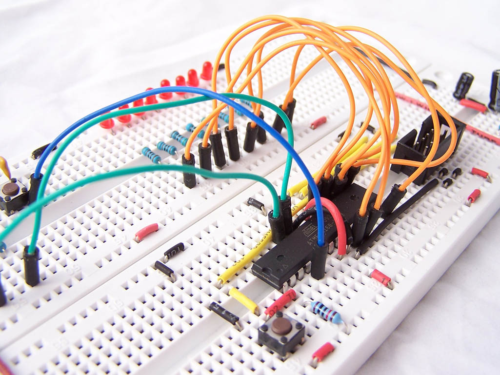
The examples in this tutorial are based on the following circuit.
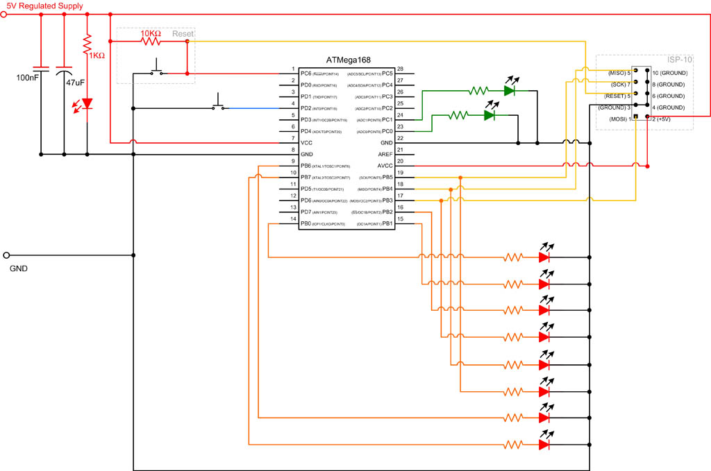
The main routine will run a continual sweep on the 8 red LEDs. When the button (the one connected to PD2) is pressed, we briefly turn on the first green LED, then turn the 2nd green LED on for 2 seconds. After the interrupt is complete we return to the sweep.
The source code for this example is…
- #include
- #include
- #include
- #define green_led0_on() PORTC |= _BV(0)
- #define green_led0_off() PORTC &= ~_BV(0)
- #define green_led1_on() PORTC |= _BV(1)
- #define green_led1_off() PORTC &= ~_BV(1)
- int main (void)
- {
- DDRB = 0b11111111; // All outputs
- DDRC = 0b01111111; // All outputs (Although we will just use PC0 and PC1)
- DDRD = 0b11111011; // set PD2 to input
- PORTD = 0b00000100; // set PD2 to high
- EIMSK |= _BV(INT0); //Enable INT0
- EICRA |= _BV(ISC01); //Trigger on falling edge of INT0
- sei();
- while(1)
- {
- sweep();
- }
- }
- void sweep()
- {
- PORTB = 0b10000000;
- for (int i=0;i<8;i++)
- {
- _delay_ms(100);
- PORTB >>= 1;
- }
- }
- ISR(SIG_INTERRUPT0)
- {
- green_led0_on();
- _delay_ms(50);
- green_led0_off();
- green_led1_on();
- _delay_ms(2000);
- green_led1_off();
- }
On line 18 you will see
- EIMSK |= _BV(INT0);
In AVR microcontrollers, interrupts are controller by a number of registers. On the ATmega48, 88, 168 & 328 the EIMSK (External Interrupt Mask Register) controls whether the INT0 and INT1 interrupts are enabled.
| bit | 7 | 6 | 5 | 4 | 3 | 2 | 1 | 0 |
|---|---|---|---|---|---|---|---|---|
| EIMSK | - | - | - | - | - | - | INT1 | INT0 |
| Read/Write | R | R | R | R | R | R | R/W | R/W |
| Initial Value | 0 | 0 | 0 | 0 | 0 | 0 | 0 | 0 |
The next line (line 19) has
- EICRA |= _BV(ISC01);
Again we are setting a register value, the External Interrupt Control Register A (EICRA).
| bit | 7 | 6 | 5 | 4 | 3 | 2 | 1 | 0 |
|---|---|---|---|---|---|---|---|---|
| EICRA | - | - | - | - | ISC11 | ISC10 | ISC01 | ISC00 |
| Read/Write | R | R | R | R | R/W | R/W | R/W | R/W |
| Initial Value | 0 | 0 | 0 | 0 | 0 | 0 | 0 | 0 |
This register determines under which condition INT0 or INT1 should be triggered. Specifically
| ISC01 | ISC00 | Description |
|---|---|---|
| 0 | 0 | The low level of INT0 (PD2) generates an interrupt request. |
| 0 | 1 | Any logical change on INT0 (PD2) generates an interrupt request. |
| 1 | 0 | The falling edge of INT0 (PD2) generates an interrupt request. |
| 1 | 1 | The rising edge of INT0 (PD2) generates an interrupt request. |
ISC11 and ISC10 work in the same way, but on INT1,
The next line (line 20) has
- sei();
By default, interrupts are globally switched off. By calling sei() we are enabling them.
Lastly we see at the bottom of our code, the ISR (Interrupt Service Routine). Even though it looks like a normal C function, it is really a macro that defines one of many functions based on the passed in parameters. You can pass in a vector and optionally a list of attributes. The list of interrupt vectors can be found in AVR libc
This routine will get called each time the interrupt is triggered. Whilst the ISR is running, interrupts are disabled by default. If you were to press the button multiples times you will notice that the interrupts are queued up and run in succession.
Note: in some tutorials or code examples on the net, you might see ISRs been defined with INTERRUPT or SIGNAL macros. These have been depreciated and are no longer supported.
Pin Change Interrupt Example
The source code for this example is very similar to the previous one. See if you notice the differences.
- #include
- #include
- #include
- #define green_led0_on() PORTC |= _BV(0)
- #define green_led0_off() PORTC &= ~_BV(0)
- #define green_led1_on() PORTC |= _BV(1)
- #define green_led1_off() PORTC &= ~_BV(1)
- int main (void)
- {
- DDRB = 0b11111111; // All outputs
- DDRC = 0b01111111; // All outputs (Although we will just use PC0 and PC1)
- DDRD = 0b11111011; // set PD2 to input
- PORTD = 0b00000100; // set PD2 to high
- PCICR |= _BV(PCIE2); //Enable PCINT2
- PCMSK2 |= _BV(PCINT18); //Trigger on change of PCINT18 (PD2)
- sei();
- while(1)
- {
- sweep();
- }
- }
- void sweep()
- {
- PORTB = 0b10000000;
- for (int i=0;i<8;i++)
- {
- _delay_ms(100);
- PORTB >>= 1;
- }
- }
- ISR(SIG_PIN_CHANGE2)
- {
- if(bit_is_clear(PIND,2))
- {
- green_led0_on();
- _delay_ms(50);
- green_led0_off();
- green_led1_on();
- _delay_ms(2000);
- green_led1_off();
- }
- }
The first change you should notice is the 2 registers we update in lines 18 & 19.
PCICR (Pin Change Interrupt Control Register) is used to determine which of the PCINT interrupts are enabled.
| bit | 7 | 6 | 5 | 4 | 3 | 2 | 1 | 0 |
|---|---|---|---|---|---|---|---|---|
| PCICR | - | - | - | - | - | PCIE2 | PCIE1 | PCIE0 |
| Read/Write | R | R | R | R | R | R/W | R/W | R/W |
| Initial Value | 0 | 0 | 0 | 0 | 0 | 0 | 0 | 0 |
PCMSK2 (Pin Change Mask Register 2) determines which pins cause the PCINT2 interrupt to be triggered. As you may have guessed, there are also PCMSK0 and PCMSK1 registers for the PCINT0 and PCINT1 interrupts.
| bit | 7 | 6 | 5 | 4 | 3 | 2 | 1 | 0 |
|---|---|---|---|---|---|---|---|---|
| PCMSK2 | PCINT23 | PCINT22 | PCINT21 | PCINT20 | PCINT19 | PCINT18 | PCINT17 | PCINT16 |
| Read/Write | R/W | R/W | R/W | R/W | R/W | R/W | R/W | R/W |
| Initial Value | 0 | 0 | 0 | 0 | 0 | 0 | 0 | 0 |
Next you should notice that the ISR uses a different vector. The PCINT interrupts use vectors SIG_PIN_CHANGE0, SIG_PIN_CHANGE1 and SIG_PIN_CHANGE2. We are using SIG_PIN_CHANGE2 because we want to handle the PCINT2 interrupt.
The PCINT2 interrupt triggers when the button is pressed and a second time when it is released. I’ve added an if statement to the ISR so the LED’s only turn on when the button is pressed.
Words of caution
Now it is time to highlight 3 common issues with interrupts..
- Timing
- Compiler optimisation
- Non atomic operations
The timing problem relates to what you may be doing with your main routine. If you are doing something that is time sensitive (like I/O for instance) and your ISR take a long time to run you could get yourself in trouble. In general it is recommended that you keep ISRs short.
Next we have the Compiler optimisation issue. When you share variables between your main routine and your ISR, you need to mark them as volatile. This lets the compiler code optimiser know that the variable can change for reasons it is not aware of. This is best explained with a code example.
- volatile int someone_pressed_the_button;
- int main (void)
- {
- setup_stuff();
- someone_pressed_the_button=0;
- while(1)
- {
- if (someone_pressed_the_button!=0)
- {
- turn_led_on();
- someone_pressed_the_button = 0;
- }
- }
- }
- ISR(SIG_INTERRUPT0)
- {
- someone_pressed_the_button = 1;
- }
If the shared variable was not set to volatile, the code optimizer might optimise away the whole if statement. After all if the variable is non volatile, we would never expect the “then” part of that statement to be executed.
The last problem has to do with the shared variable. ints are a 4 byte data type and we are working with an 8 bit microcontroller. Consider what happens if we were part way through updating the shared variable when the interrupt was triggered. We deal with this by putting the sensitive code within an atomic block.
- volatile int someone_pressed_the_button;
- int main (void)
- {
- setup_stuff();
- someone_pressed_the_button=0;
- while(1)
- {
- if (someone_pressed_the_button!=0)
- {
- turn_led_on();
- ATOMIC_BLOCK(ATOMIC_RESTORESTATE)
- {
- someone_pressed_the_button = 0;
- }
- }
- }
- }
- ISR(SIG_INTERRUPT0)
- {
- someone_pressed_the_button = 1;
- }
More Information
AVR libc
ATmega48/88/168/328 datasheet
No comments:
Post a Comment