Understanding Interrupts
Probably you won’t be able to find a microcontroller without interrupt capability. These are essential attributes of any modern microcontroller or processor. They may seem confusing and tricky at first glance, but during the time you will find out that normalMCU operation is impossible without interrupts.
Interrupts can be easily compared to real life events. Look around – all your activities are full of them. For instance you are reading this tutorial and find it interesting so you are all in it. But suddenly you cell phone rings. What you do? You remember last stroke you’ve red and answer the phone. Once phone conversation is over you get back to your reading as nothing happened. Well this is only one example of interrupt to give some visual clue what interrupts are.
Interrupts in microcontrollers are very similar to this example so there should be no problem to understand them. Lets get more specific and closer to hardware.
Microcontrollers usually have multiple interrupt sources available. For instance Atmega328 has 26 of them. So program flow can be interrupted by various events like external pin go low, timer overflow or ADC conversion complete. If set properly these events will take over program flow once occur and give back resources once they’ve been serviced. As we mentioned microcontroller can have multiple interrupt sources. AVR is equipped only with hardware interrupts. Other microcontrollers may have software interrupts as well. Hardware interrupts mean that they can only be generated by hardware events like pin change or other. If you look in to AVR datasheet you will always find a table of interrupt vectors like this:
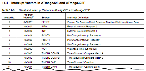
This table is programmed into microcontroller memory along with your program as it is a reference table containing address of interrupt service routines – a special functions that will be called once interrupt will occur. As you can see in table there is a column “Program Address” these are locations in flash where a interrupt service routine is located in program memory. For instance at the very beginning of flash (0×0000) there is a reset address stored. This means when MCU is powered program will look at this location and jumps to place where tour main() program starts. When programming in C – interrupt table is created automatically during compilation, while ASM programmers have to set this table by themselves. Without going in to details it is worth mention that interrupt vectors can be stored in boot section depending on fuse settings – so bootloader could use benefits of interrupts. But leave this for some time later.
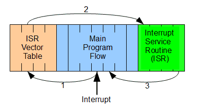
In the image you can see simple interrupt handling sequence. Let’s say our program is doing some tasks in Main program flow. When interrupt signal occurs at any given moment of program flow it stops at current location, remembers next operation address and then loads program counter with ISR address (1) stored in ISR vector table. From this moment interrupt handling function is performed (2). Once it’s complete program counter is loaded with next interrupted program operation (3). So main program actually doesn’t know that interrupt has occurred and continues normally. This is very simplified illustration of interrupt as we didn’t mention preserving of register values during interrupt and so on. But lets leave this when we get to the code examples.

